Interfacing with ABB Robot Arm I/O Unit

This time I will talk about my struggle to use the I/O unit on the ABB IRC5 Compact Controller. Online resources are not as abundant as other robotics arm like Universal Robot. So I hope this article can help.
Knowing your Hardware
The configuration of the robot arm is pretty complex. After assembly and wiring up, we can start working on the configuration.
1) For the standalone route, we can control the robot arm with FlexPendant. FlexPendant is essentially a device with a screen and joystick where you can carry around and interact with the robot.
2) For the PC route, we can connect use the RobotStudio from ABB. The added benefit of using RobotStudio is that it provides a virtual(simulated) robot to work on. The workflow is to program everything with the virtual controller and sync it to the real one. However, keep in mind that some configuration cannot be transferred with a simple click and thus make sure you double check everything.
Installing ABB RobotStudio
To use the advanced features of RobotStudio, you need a license from ABB. The year 2020 is special that ABB relaxed the requirements and allowed everyone to download the RobotStudio premium version. Contact ABB Support if you need the license.
Finding the Datasheet for your Hardware
This is one of the hardest part of the journey. ABB does not include any useful diagram or manual together in the shipping crate, and the online documentation is also incomplete. In my case, I got a IRC5 Compact Controller and the “datasheet” is more like a sales brochure.
I come across this 3HAC049406-003 document after quite a while of Google Search. This includes the drawing and schematic of the device.
The I/O component we get in the IRC5 Compact Controller is DSQC 652 I/O Unit, which appears on page 23.a ~ 23.b in 3HAC049406-003.
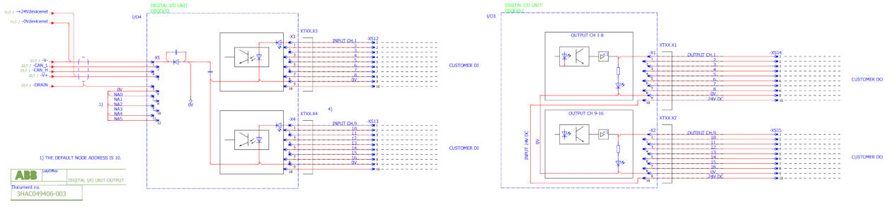
From this schematic, we can notice a few things:
- The physical connection is labeled
CAN_HandCAN_L, which indicates that the device is external - The corresponding physical socket is
XS12&XS13for Inputs,XS14&XS15for Outputs - The I/O is isolated using opto-couplers
- The I/O channels are labeled staring with
CH.1 - The Keyword
24Vappeared twice,24VdevicenetandINPUT 24V DC
which can explain a lot of confusion later in the programming part.
Follow Existing Online Resources
I started following Guide: How to Set Up I/O on an ABB Robot with an IRC5 Controller on the ABB forum. PDF version archived here, just in case. It was written back in 2016 so stuff may have changed. Here is my updated version.
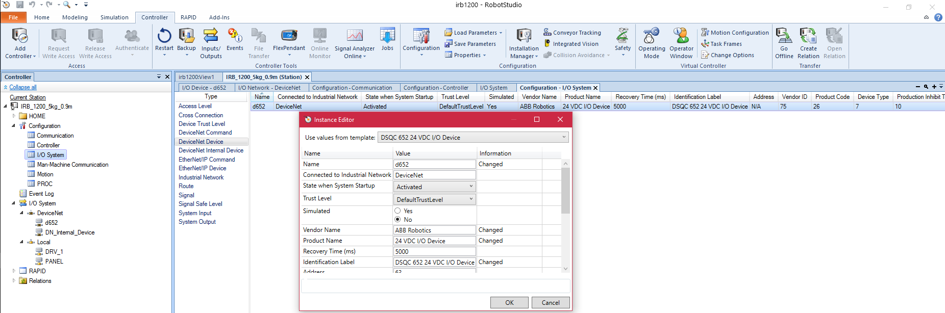
Adding ABB DSQC652 to the Virtual Controller
- Click the
Controllertab at the top - On the left sidebar, select the current station (
IRB_1200_5kg_0.9min my case) and navigate toConfiguration > I/O System(double-click) - In the main window, on the refreshed content, find the
DeviceNet Deviceon the left - In the pop-up window, choose form the top drop-down menu
DSQC 652 24 VDC I/O Device - Inspect the default value and click
OK - Remember to do a
Warm Restartfor the config to take effect - After that, you can edit the
Signal(as in step 3) and register our custom signal - In the
New Signal...prompt, choosed652in theAssigned to Deviceand fill in the rest
Configuring the Signal
Just keep in mind:
Assigned to Devicechoosed652Device Mappingstarts with index0Invert Physical Valuerelated options can be useful depending on your hardware
At this point, you can start your program in RoboStudio with the simulated I/O.
Choosing Controller tab, and expanding the left sidebar, you can find the I/O System options (NOT Configuration > I/O System). Your newly constructed I/O signal should appear here after a Warm Restart. The status of the I/O can be toggled by double-clicking on each item.
Configuring System Input & System Output
You can also configure the I/O to interact directly to the system (instead of your RAPID program). Clicking Configuration > I/O System, on the main window we also have System Input & System Output. Here we can configure the I/O to perform system level actions, such as Reset Emergence Stop, PP to Main, Motor On and Start etc.
Deploying to the Physical(Real) Hardware
From the forum post, we can see the author struggle a lot when setting up the hardware.
Fun fact! The internal logic of the DSQC652 is powered, but the digital outputs are NOT. You have to power them externally by connecting 24V and 0V (GND) …
Another fun fact! By now you’re probably realizing that every time I say “fun fact” I actually mean “days of fury, frustration, wailing and gnashing of teeth”. Remember when we were creating our Signal and we set “Unit Mapping” to 0? A zero in Unit Mapping corresponds to the pin 1 on the X1. A one in Unit Mapping corresponds to pin 2, etc. Real intuitive, I know.
This is very valid concerns if you don’t have the schematic in hand or not very into electronics (like me).
So there is the list of tricky stuffs from my perspective
- The I/O part of the
DSQC652requires external power, as a result of opto-isolation- Connect to the internal power supply (
XS16inIRC5 Compact) OR go external power if you need more current - The opto-coupler need roughly takes
5mAwhen the Input is connected directly to24V, giving the estimation of the current limiting resistor~5kΩ - The minimum
HIGHinput can go as low as10Vbase on my trial & error (caution needed!!)
- Connect to the internal power supply (
DSQC652is an external device on the DeviceNet- If you accidentally short
24VtoGNDon internal power, the device will go offline - A
Warm Restartis needed to bring to online again
- If you accidentally short
- The numbering scheme is different in the configuration vs hardware
- On the software side, the
Device Mappingstarts from0 - On the hardware side, the
I/O channelsare labeled staring withCH.1
- On the software side, the
- Sync the virtual and physical controllers (RAPID)
- In the top
RAPIDtab, doSynchronize to RAPIDto update the RAPID file - Connect the physical controller ot the PC, and
Request Write Accesson the correct target - Right-click one of the stations and
Create Relation - Do the
Transferand double check the direction of upload is correct - Always check on the FlexPendant if the settings/program is updated. For example, the RAPID program may not be updating (after upload) when the
Production Windowis active on the FlexPedant Warm Restartis needed when you modifiedSignal
- In the top
- Sync the virtual and physical controllers (I/O Systems)
- In the previous parts, I mostly highlighted the configuration of the virtual controller,
you have to transfer all the configuration to the real one (in parallel to your RAPID program) - This should be as simple as right-clicking
ConfigurationandLoad Parameters..., the restoring on the other one - In case this route doesn’t work, just manually create the entries (on FlexPendant, or RobotStudio after
Request Write Access) - Make sure you have the matching
Signal Name
- In the previous parts, I mostly highlighted the configuration of the virtual controller,
Closing Thoughts
ABB robot arms are generally more industrial and designed to be interfaced with Programmable Logic Controller(PLC). Therefore, the control and UI interface is much harder then some modern alternatives like Universal Robots. I can also find some packages supporting controlling ABB with ROS, but I never have time to look into.